        How to Build a Frequency-Stabilized HeNe Laser Doug Marett
Introduction
HeNe
lasers are excellent sources of coherent light for optical experiments.
One issue with these lasers though is that the power and frequency of
the beam tends to fluctuate due mostly to thermal instabilities that
cause subtle changes in the length of the laser tube. Many experiments
require stable optical beams with a frequency stability within +/- a
few MHz of their center frequency. The following is an outline for
constructing a two-mode stabilized HeNe laser that will rival the
performance of a system costing several thousand dollars. The expected
precision will better than +/-0.1 part per million variation in optical
frequency once locked. Basic
Requirements:
One
needs to obtain a good two mode laser tube, some wire for the heater
coil, a beam-splitter for the waste beam, and some photodiodes to
detect the waste beam intensity. Three electronic circuits are also
required: 1) A controller circuit 2) A power supply 3) A HeNe Laser power supply ripple
reducer One place to obtain a HeNe laser
tube, wire, beam-splitter and photodiodes is from a kit supplied by www.repairfaq.org.
This consists of: 1) An ~ 1mw, 10" Laser tube that had
been tested and found to be well behaved so far as mode sweep was
concerned. 2) Mounting brackets and a Laser
power supply. 3) A pair of silicon photodiodes for
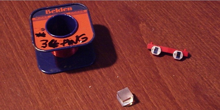
the dual mode beam sampler. 4) A spool with enough wire (#34 AWG)
to construct the heater.
Figure 1: #34 Wire spool, beams-splitter, and pair of photodiodes.
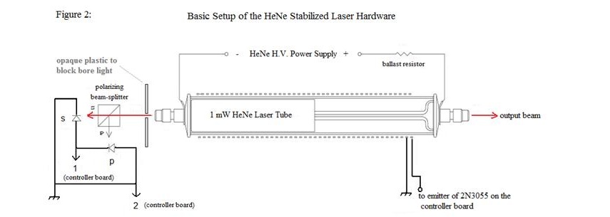
A diagram showing the arrangement of the laser hardware as it is to be mounted in the laser enclosure box is shown in Fig 2: Figure 2A:
Frequency-Stabilized Laser Controller
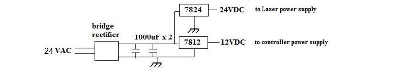
Circuit: This controller circuit was a modification of one of the circuits described at www.repairfaq.org. The main chip is an LM258 or LM358. The signal from each photodiode is compared and the difference amplified to drive the heater on the laser tube. When the diodes are balanced (the light intensity from each mode of the waste beam is equal) the heater is turned off. A beam balance control is used to add a bias to this zero level so that the stabilization point can be anywhere from maximum on mode 1/minimum on mode 2 to maximum on mode 2/minimum on mode 1, and the voltage on the output of the LM258 is monitored with a multimeter. Figure 2B: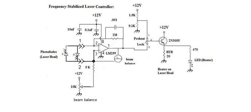 The power supply circuit is as follows: Figure 2C:
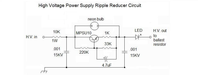
A third circuit, the ripple reducer circuit, proved to be essential in removing noise from the power supply that would otherwise get into the beam. This circuit is designed by Sam Goldwasser's and is described on his site www.repairfaq.org site. It is placed in the positive H.V. line going to the laser with the output of the ripple reducer circuit connected before the ballast resistor that connects to the laser tube. Figure 2D:
Instructions for Assembly of the Laser tube Hardware: 1) Remove any paper or aluminum foil from the walls of the tube to insure good coupling to the coil. 2)
Winding the heater coil - should be would bifilar style. A length of
the #34 AWG wire should be measured with a multimeter to find the
length that most closely equals 20 ohms. This length is folded over so
that you have the two strand ends at one end and the fold at the other
end. The folded over end can be temporarily taped to one end of the
tube (about 2cm from the end of the tube) and carefully wind the two
stands side by side around the tube, evenly spaced, to about 2cm from
the far end (generally this ends up being 1 layer of windings).
Electrical tape can then be wound over the coil to hold it in place,
and help insulate the tube. Once
the coil is complete, the two ends of the wire can be stripped bare,
one wire soldered to ground, and the other is connected to the
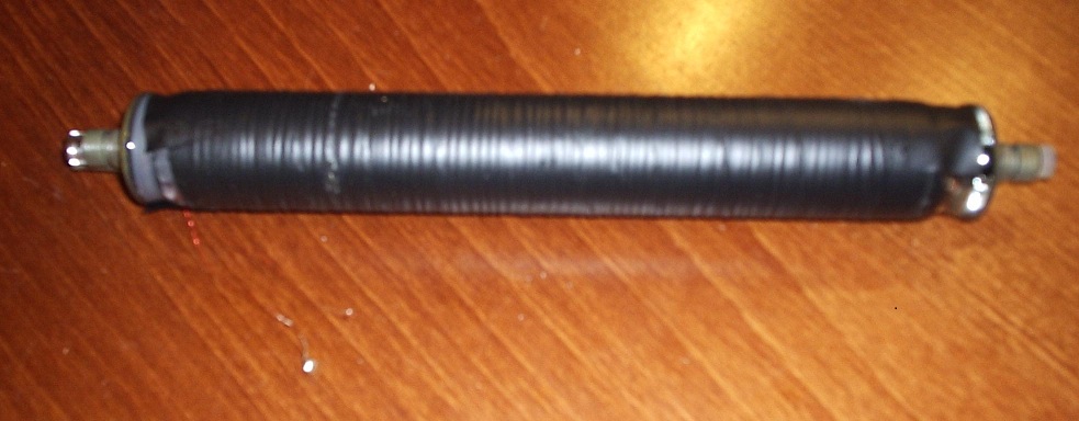
controller board (to the emitter of the 2N3055). Figure 3: The completed HeNe tube with the bifilar heater winding.
3)
The completed tube is then mounted with its holder into an enclosure
box. The beam-splitter was seated in the path of the waste beam such
that each polarized mode would exit towards its respective photodiode.
The photodiodes and the beam-splitter were mounted together on a wooden
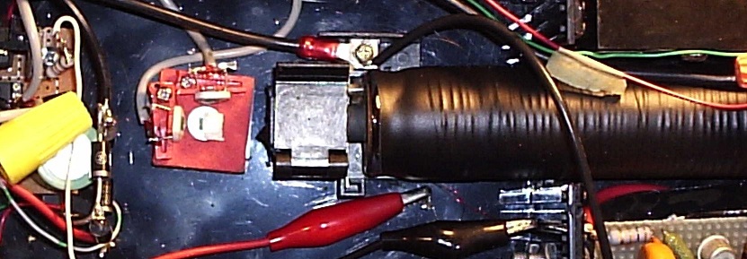
block, that was screwed into the base of the laser enclosure. Figure 4: Detail of the photodiode arrangement opposite the waste beam exit.
The red and black alligator leads at
the bottom of Fig. 4 are the connections to the heater from the
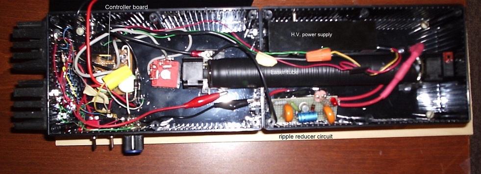
controller circuit. Fig. 5A: The complete laser with the controller circuit on the left.
The
7812 and the 2N3055 are mounted on heat sinks at the back of the unit.
The controller board is at the back, along with the on/off switch,
power LED, lock ON/OFF switch, and the beam balance potentiometer. The
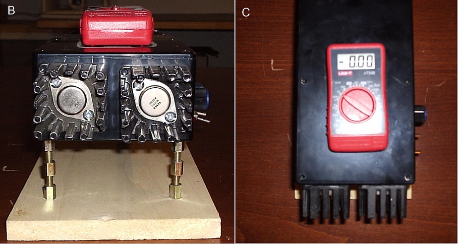
ripple control circuit is at the front bottom. Figure 5B and C: Detail of heat sinks and multimeter mounting.
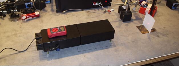
Figure 6: The completed HeNe stabilized laser in operation:
Test of the Laser for
frequency stabilization:
The laser is put on pre-heat during
warm-up for
about 30 minutes (heater switch in the down position). As the laser
warms up, the meter shows that the intensity of the beams switches from
+5V to -5V on the meter, rapidly at first, and then slowing down as the
laser warms up. The heater switch is flipped up to lock when the laser
is passing through the desired balance ratio between the beams. This
locks the intensity of the beams at approximately the intensity they
are at when the lock is applied. The potentiometer adjusts the ground
potential (offset) and thereby can adjust the beam balance after lock
to a more suitable lock position. After lock, the meter fluctuates by
around 0.05V in the short term, more in the long term (the lasers can
be knocked off their lock point by a sudden breeze, etc, so thermal
insulation is important for best performance).
The
beat frequency between the two modes of each laser constructed was
around 688 MHz, and was determined by heterodyning down the UHF beat
signal into the RF range where it could be measured with a standard
oscilloscope. . The difference in center frequency between the two
lasers was determined to be around 420KHz . This was determined by
beating the two laser beams from two separate lasers together at the
photo-detector, and determining the sub-beat frequency. The frequency stability of each laser was determined by beating the beam of one laser with another at the photo-detector. The lasers were allowed to stabilize for about 30 minutes, and then were each locked at a mode spacing that was visible on the oscilloscope without heterodyning. In this test the difference between the two modes of the same polarization from each laser varied between around 5MHz to 10 MHz over the course of several minutes. The average drift for each laser would then be about half the drift value, since the drift is the combination of both lasers together. Samples of the oscilloscope traces are shown in Fig. 7. Figure 7: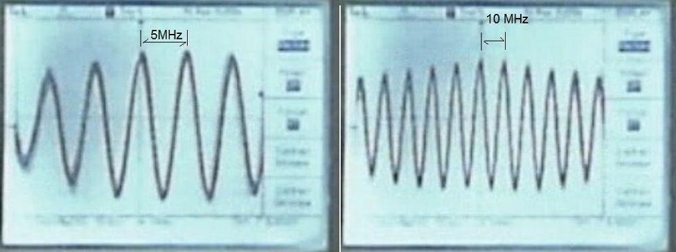
The actual experimental setup on the optical table is shown in figure 8. Figure 8: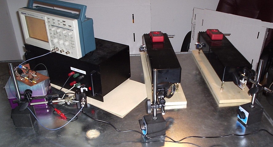
The final frequency stability was estimated to be on the order of 2-3 MHz per laser over a period of several minutes, based on the combined instability measured above of ~ 5 MHz. This is quite good, since the center frequency of each laser is around 4.74E14 Hz.
************ |